
Lukas Henkel
@QVHenkel
All things 3D | Rendering | Simulation | Electronics | StartUp | CEO engineering services company - views are my own
You might like


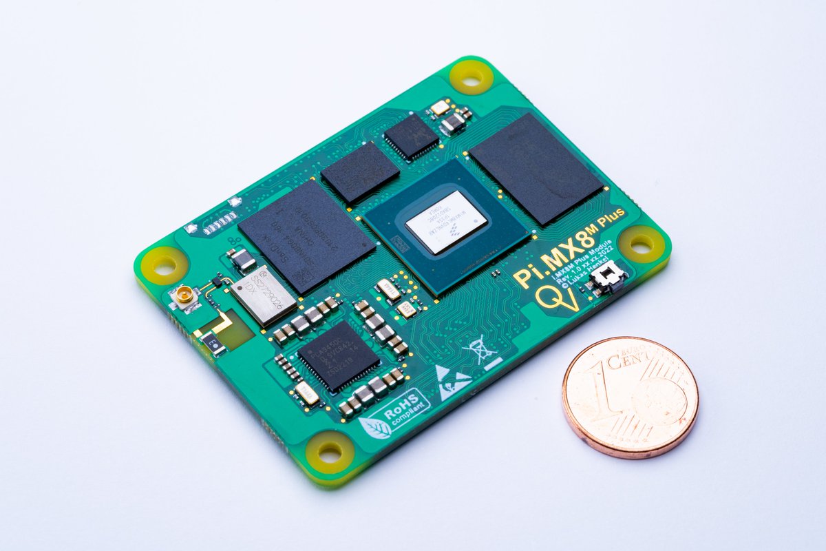
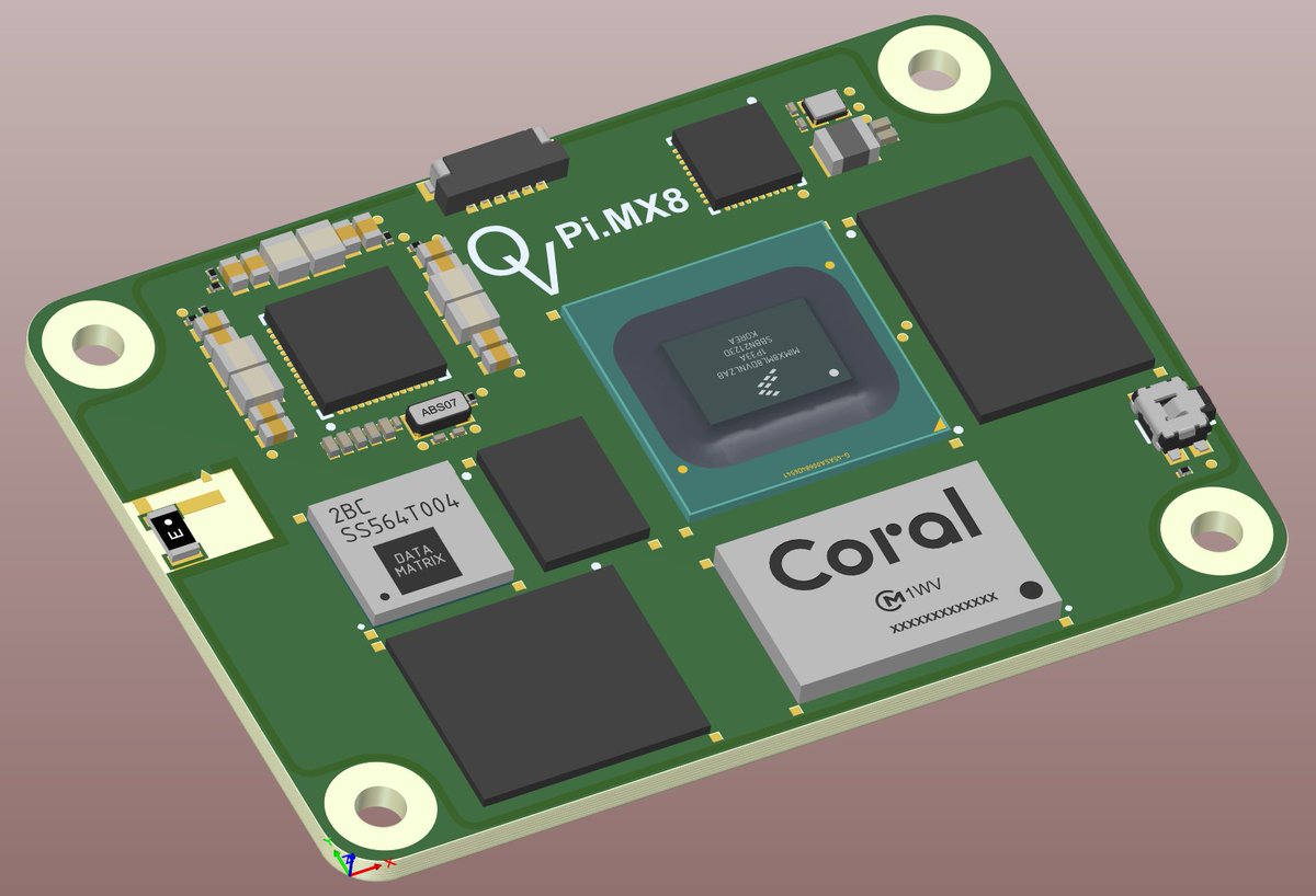
I am in the process of getting the production version of the open-source Raspberry Pi CM4 compatible module based on an iMX 8M plus up and running. If you are interested in this module, check out the Crowdsupply pre-launch page 😊
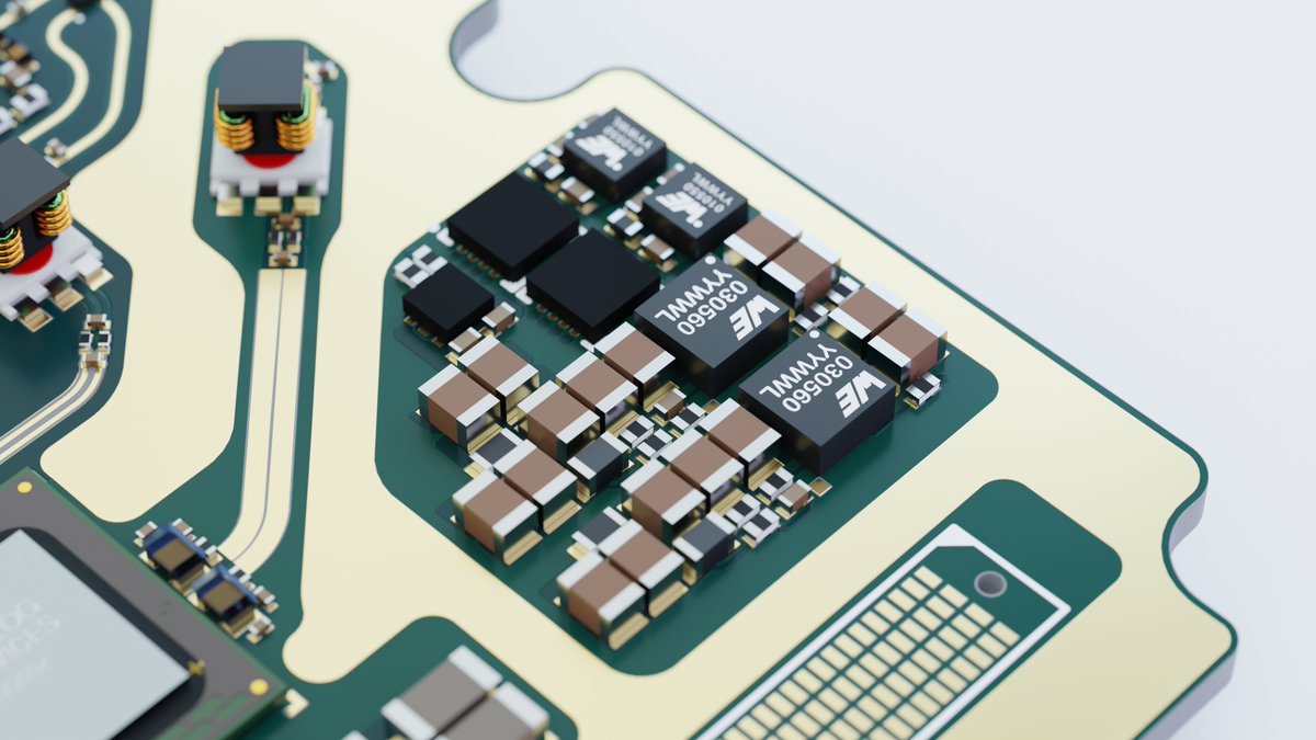
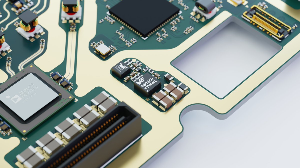
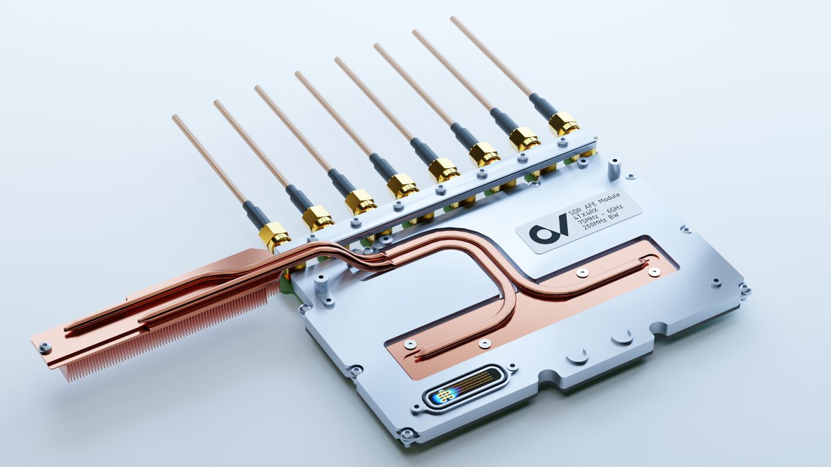
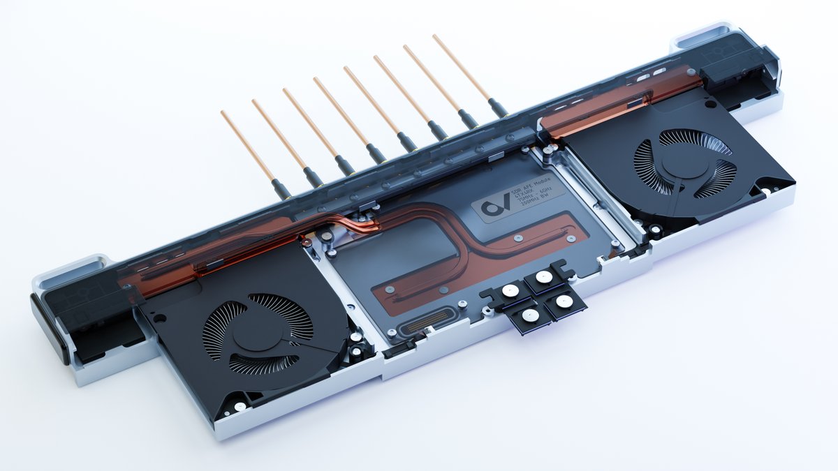
The SDR AFE board is a power module paradise😄The small formfactor is nice and thermal management will be easy in this case
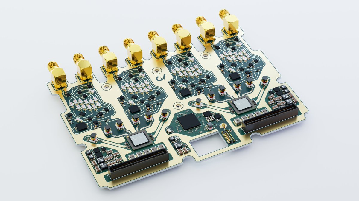
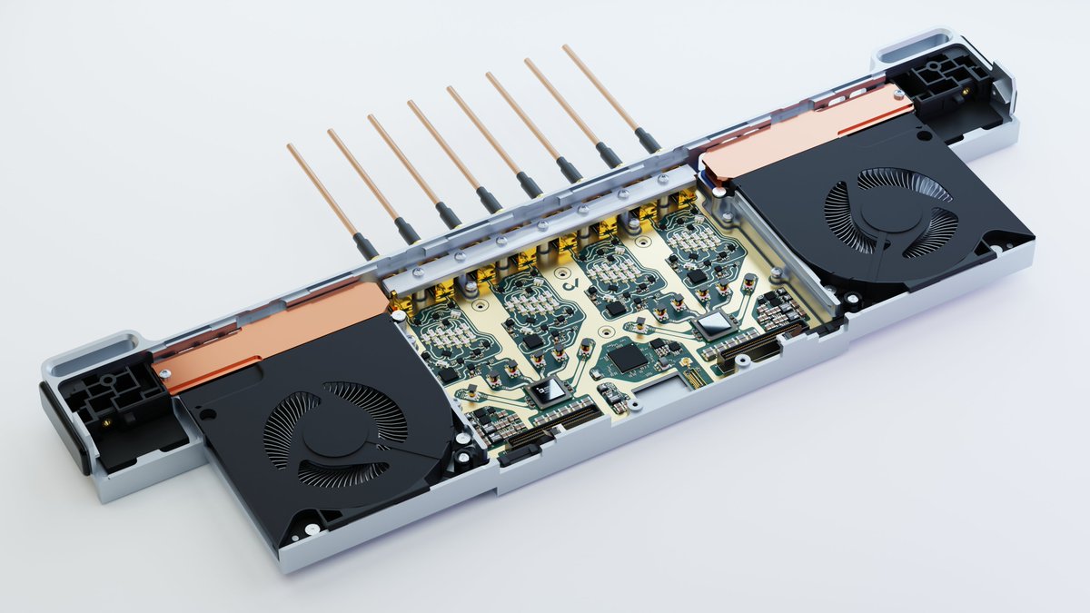
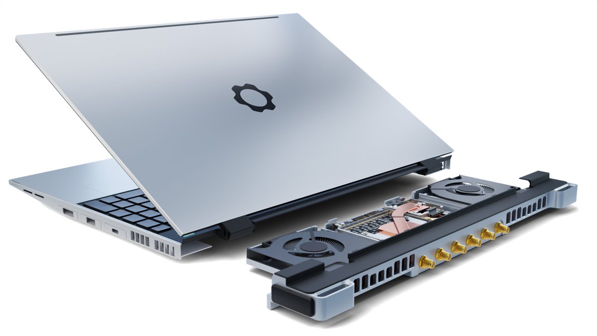
The design of the new frontend for the Framework Laptop 16 SDR module is almost complete 🙌
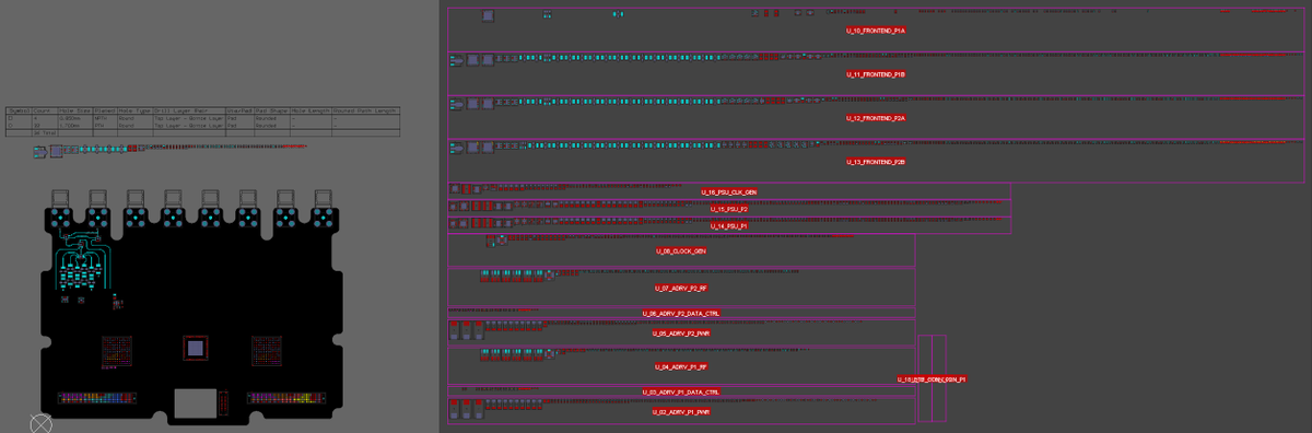
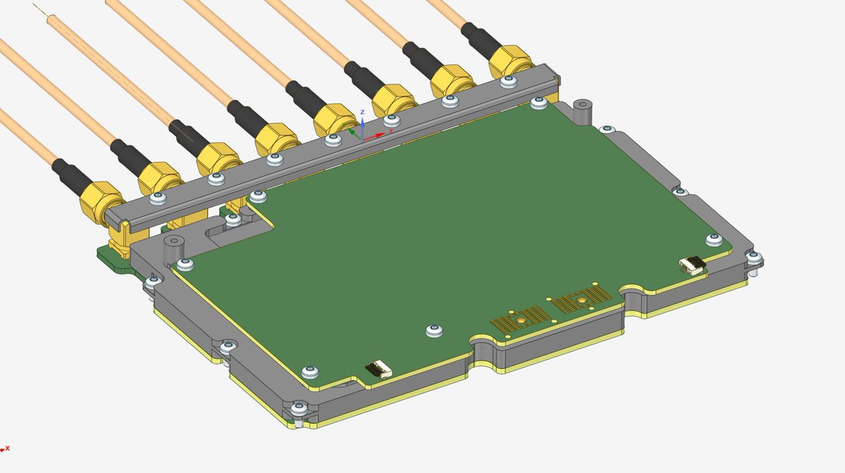
I decided to use a buried via stackup, since the entire transmit chain (only the receive chain is shown here) will have to be located on the bottom side of the AFE board
Schematics for the new revision of the Framework Laptop SDR module analog frontend is done. Now I just need to figure out where to put the 1700 components 😬
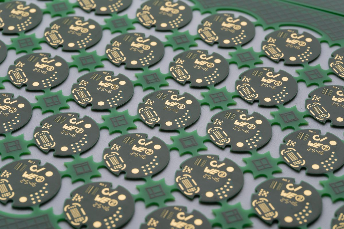
The new PPG sensorboard revision arrived. Time to try manually assembling 01005 parts 🤏
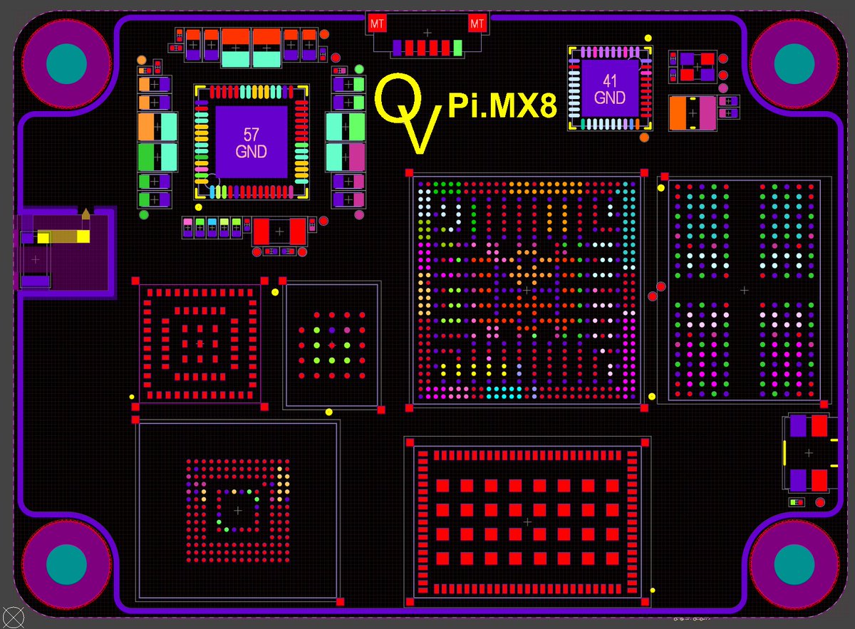
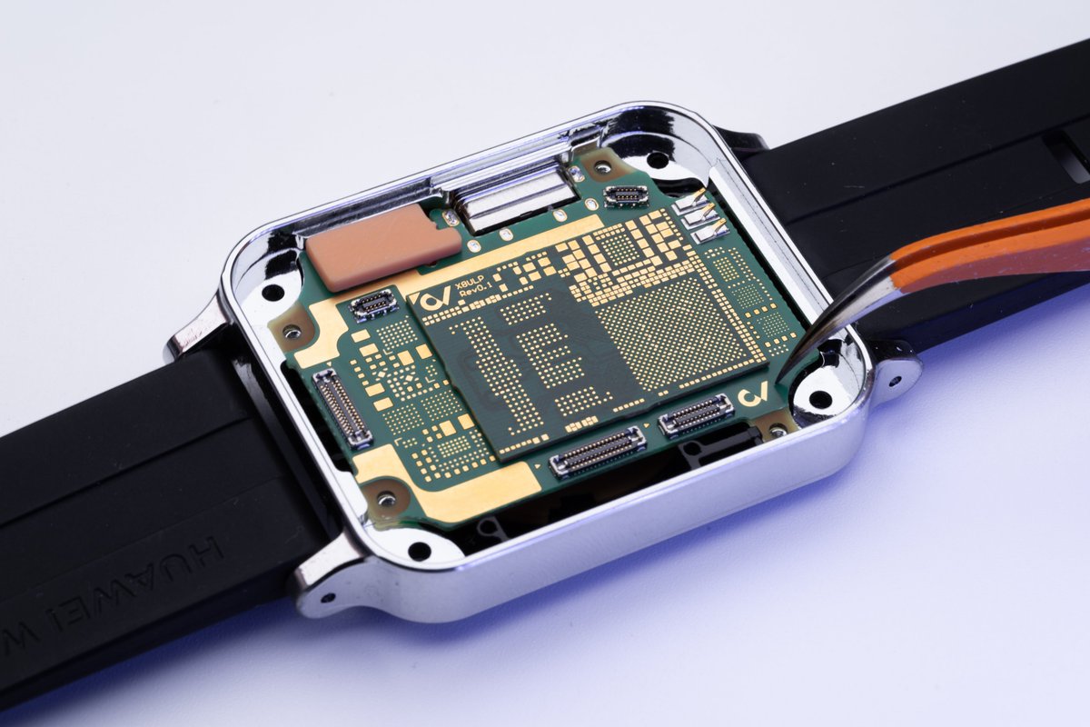
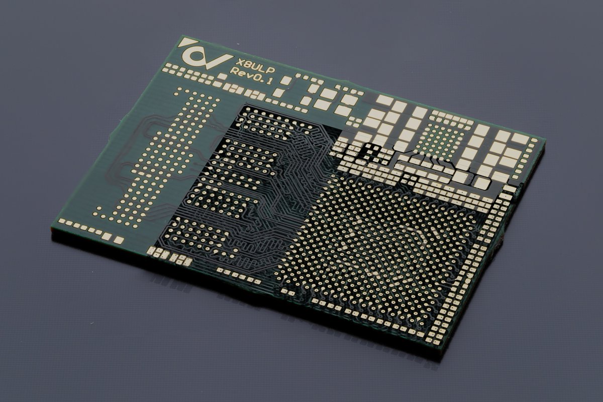
Symmetric DRAM layouts save so much time. Even if the controller pinout is not symmetrical (which it rarely is) there are still so many swap options that it makes sense to mirror most of the escape routing

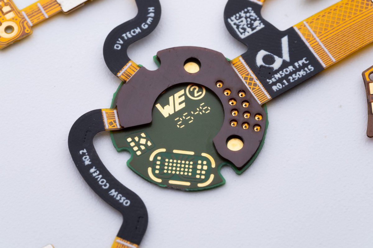
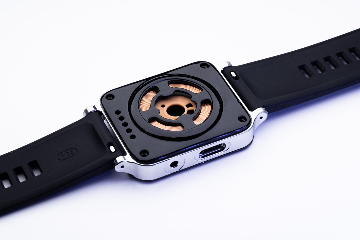
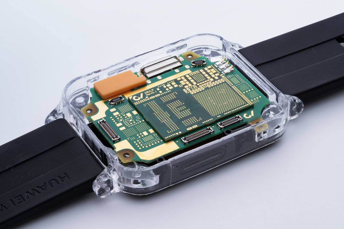
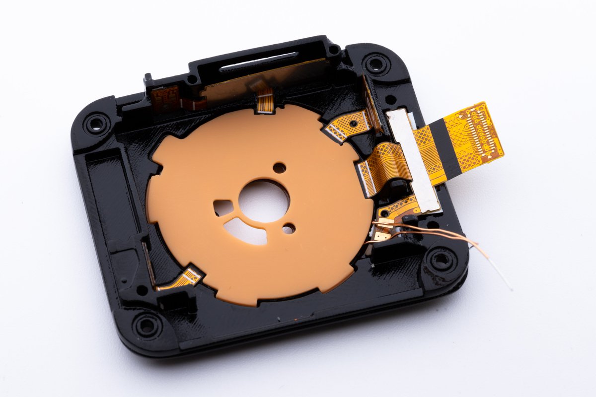
I received some more prototypes for the open-source smartwatch, including a few machined enclosures
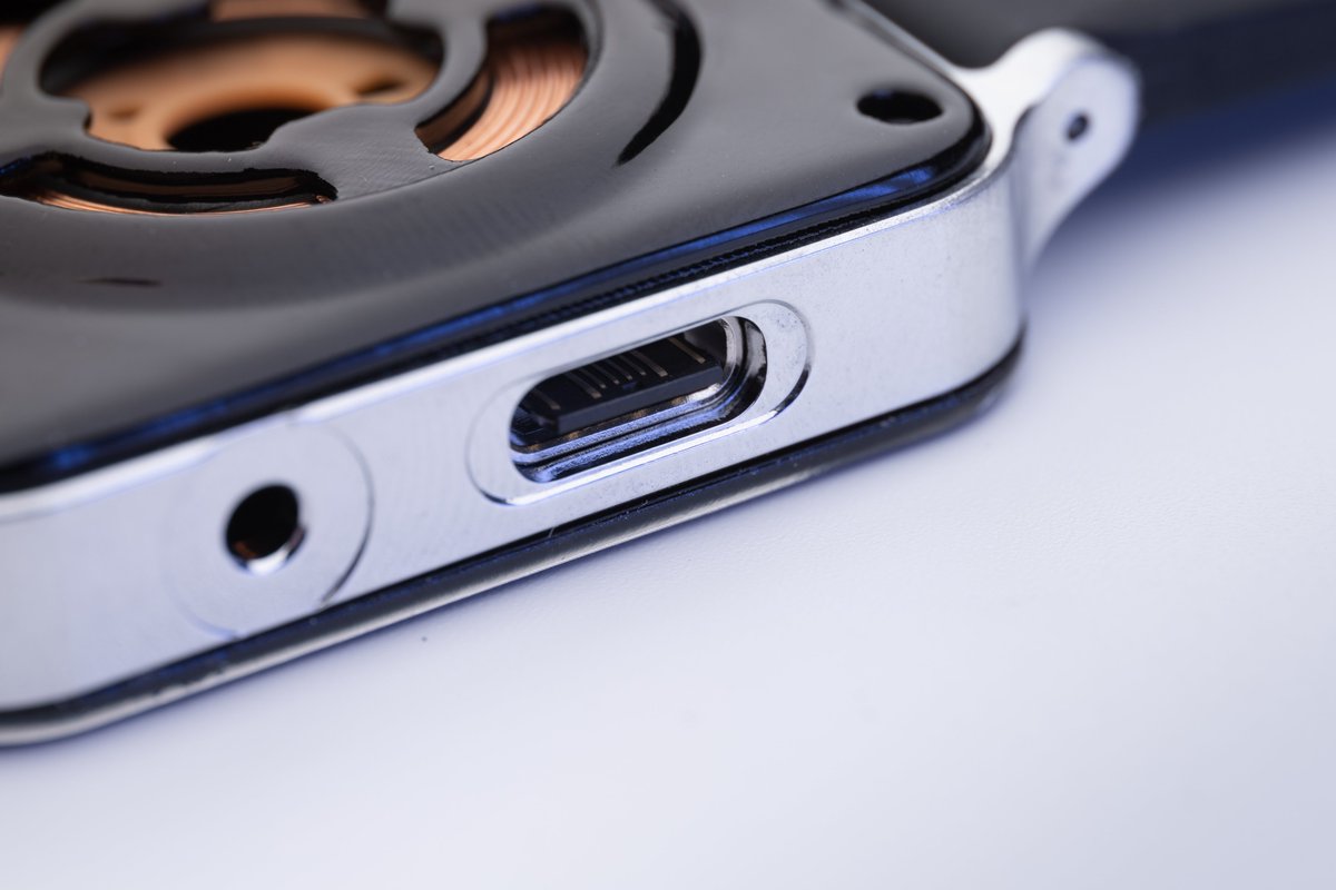
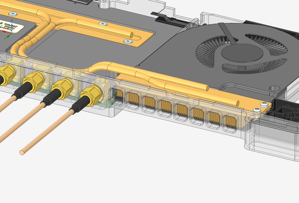
Hopefully the EMI gasket around the connector can contain the fields. I couldn’t find a fully shielded of-the-shelf connector with a stacking height of 6 mm, a high pin density, and one that is suitable for up to 24 Gbps.
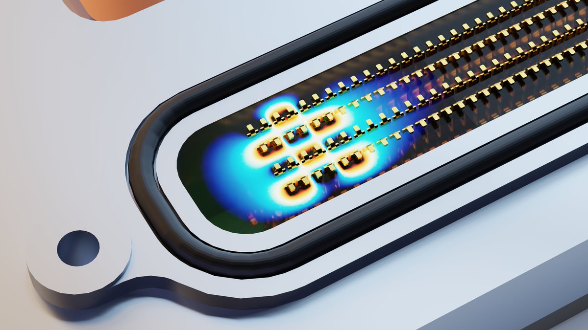
In the updated SDR implementation, I am using a fully shielded board-to-board connector for the two JESD interfaces and control signals. This is much cleaner than the previous FPC implementation


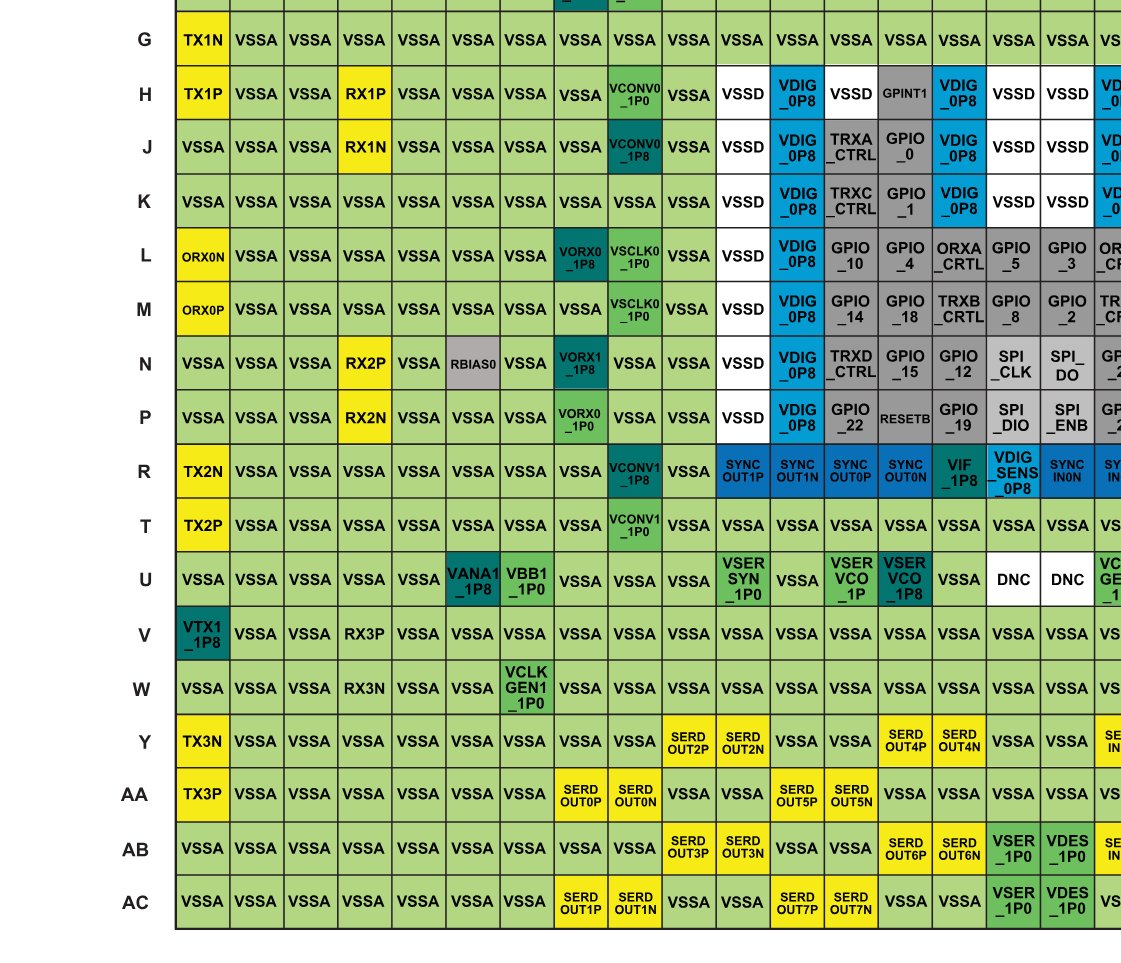
It took me way too long to find RX3 expecting it to be highlighted yellow like the other RX channels 😅
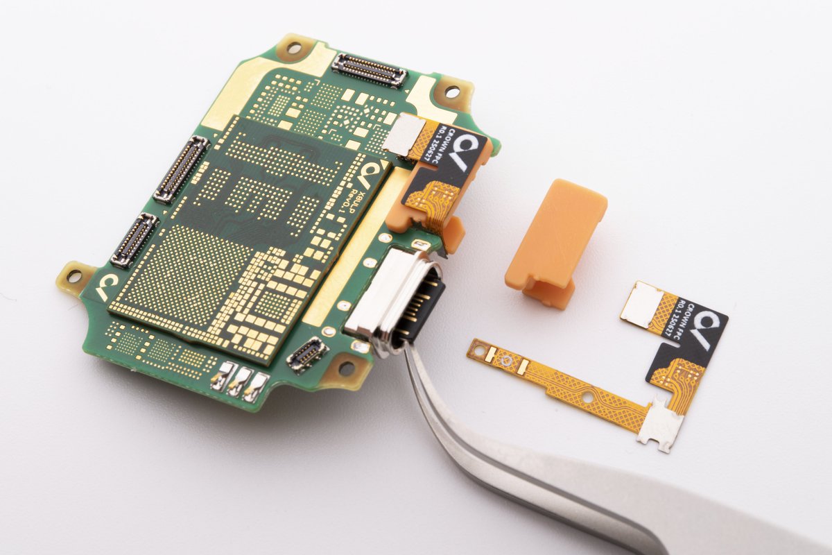
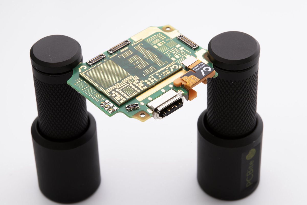
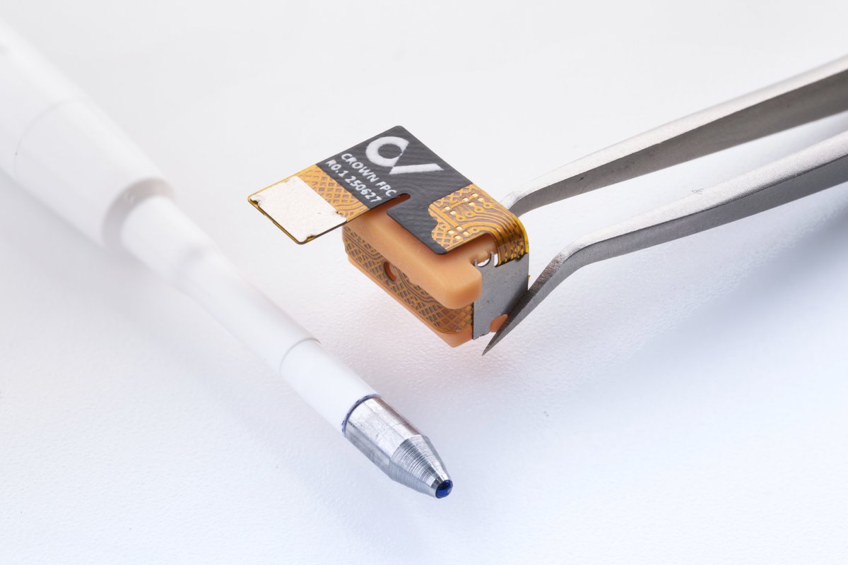
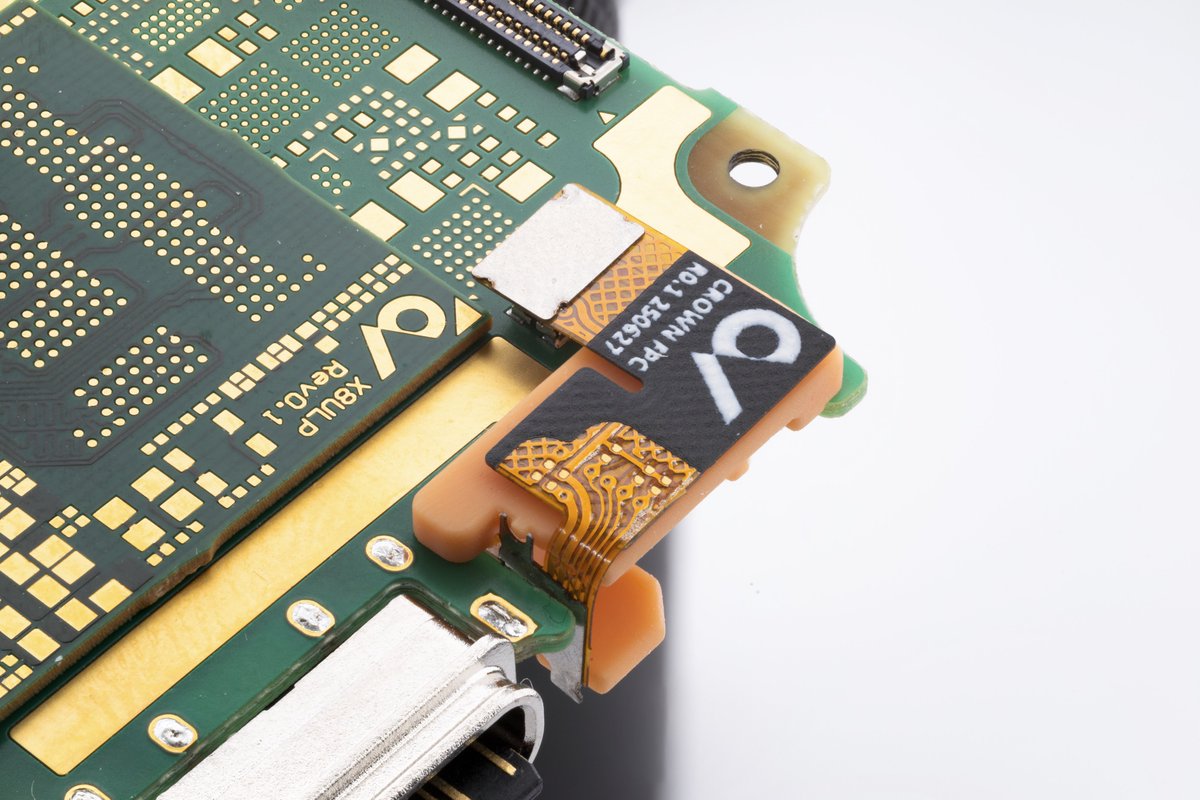
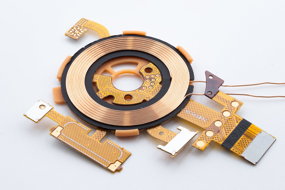
Assembling the digital crown FPC for the open-source smartwatch. The whole assembly is only 9mm wide 🧐
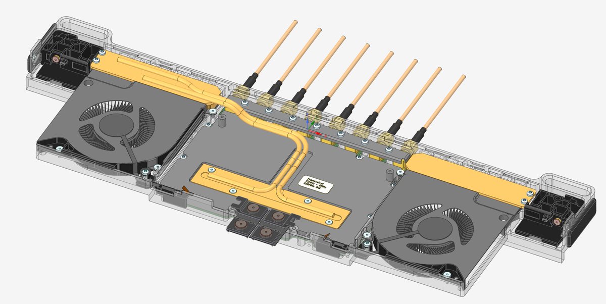
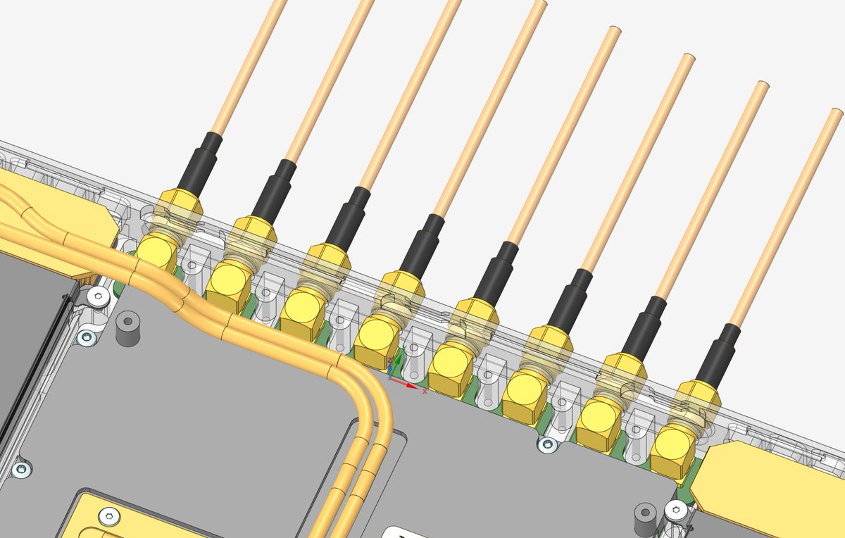
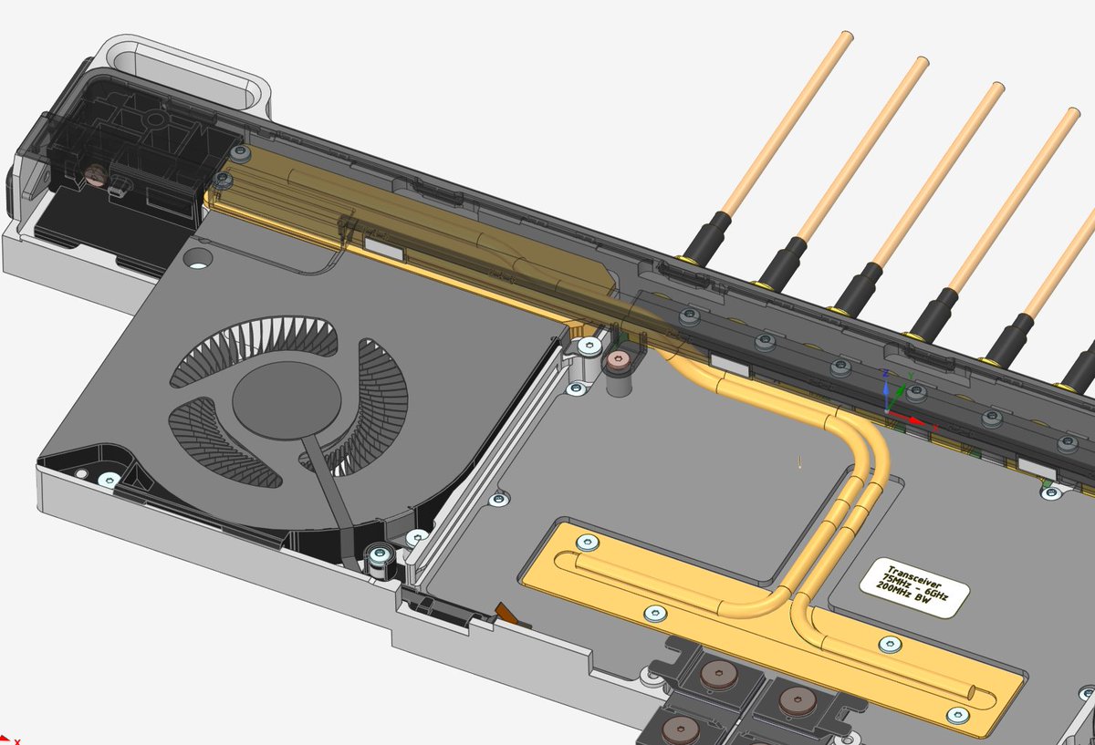
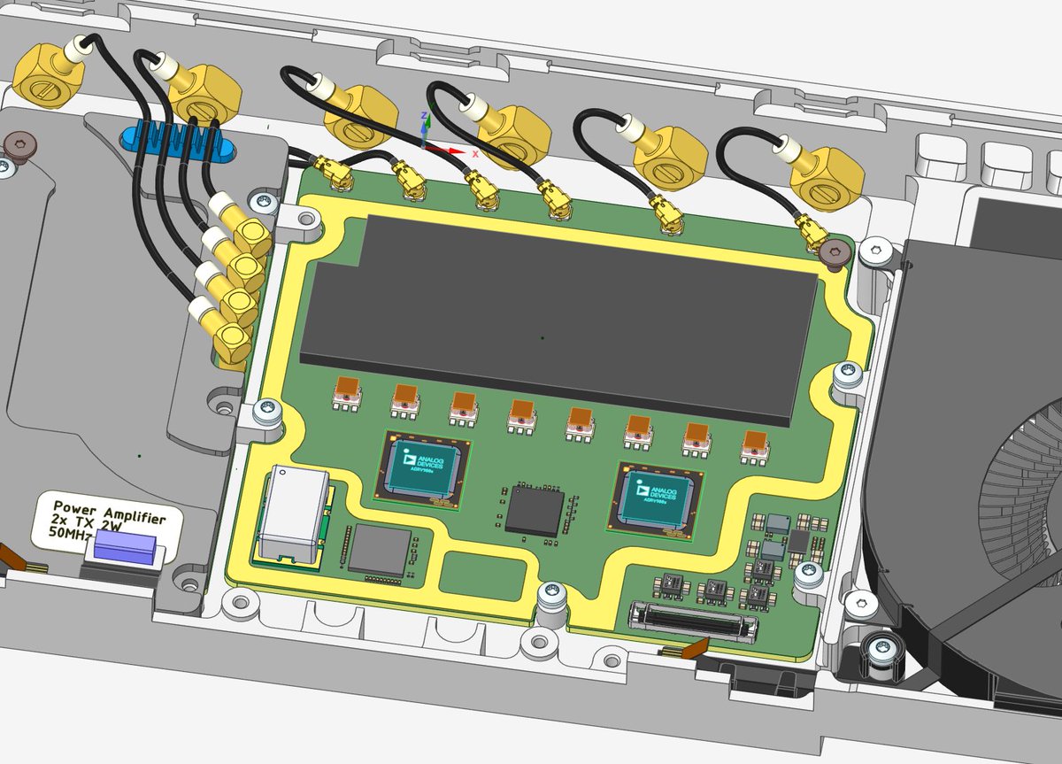
I had to combine the PA and AFE in the Framework laptop SDR. The split approach took too much space away from the filter banks. Although less modular, the new implementation allows for 4x RX and 4x TX, and is a much cleaner mechanical integration. I also switched to skived…
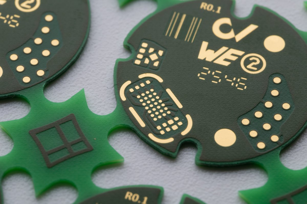
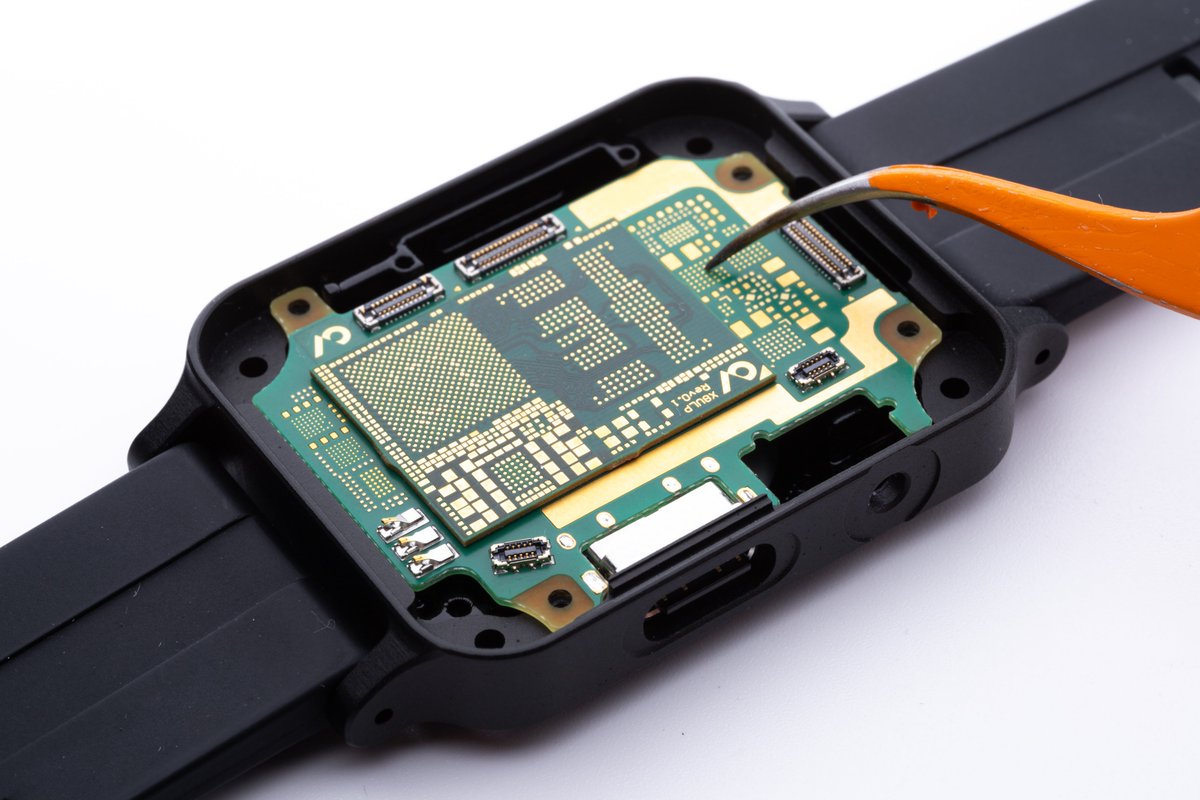
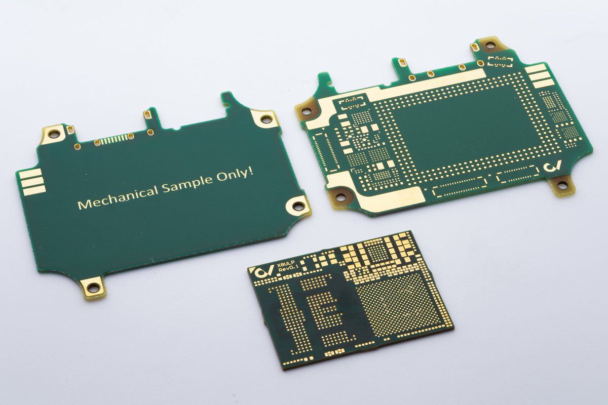
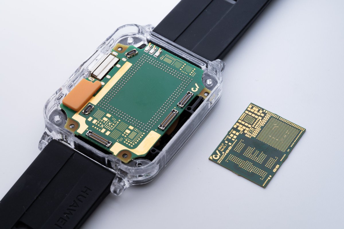
It's been years since I last ordered a two-layer board. Even this time, it was only for a mechanical test fit of the open-source smartwatch carrier board 😅 Four- and six-layer boards have become so cheap that they are my default choice for any simple project
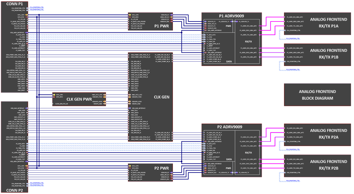
If you like fancy schematic symbols, you can copy block diagrams from datasheets. Just import the PDF into Inkscape, tidy up the block diagram and export as an EMF file. Altium can read and scale EMF files with a transparent background
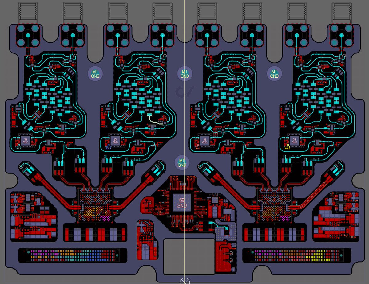
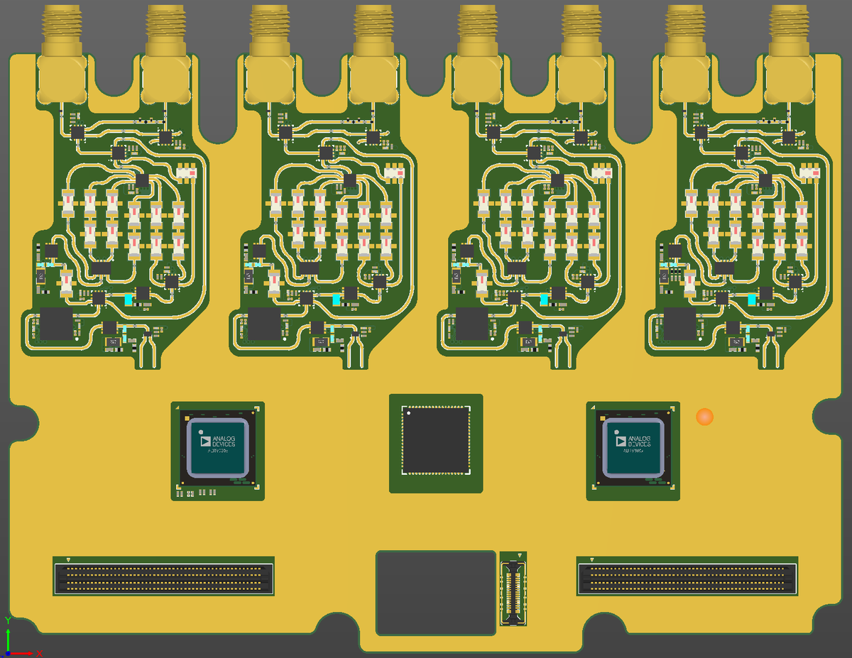
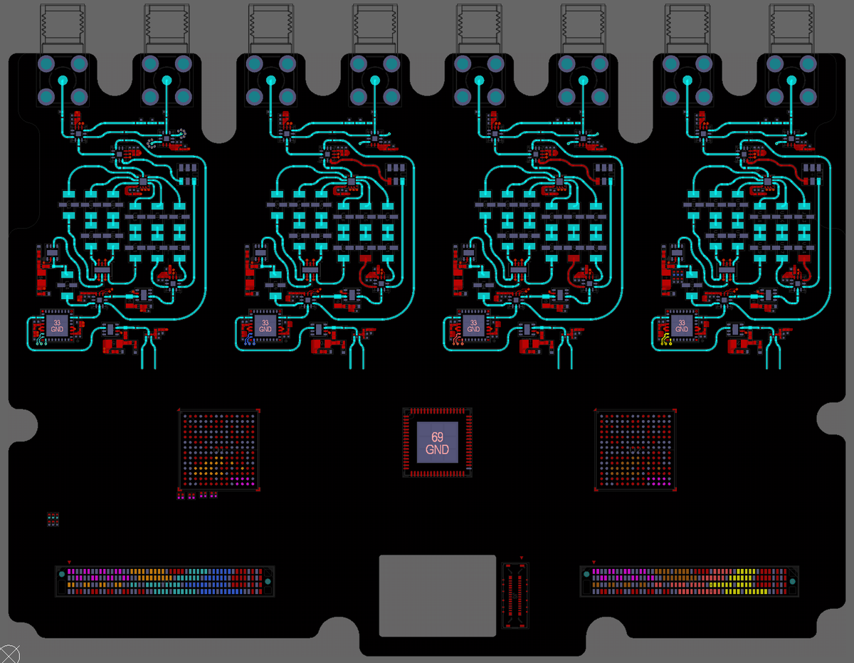
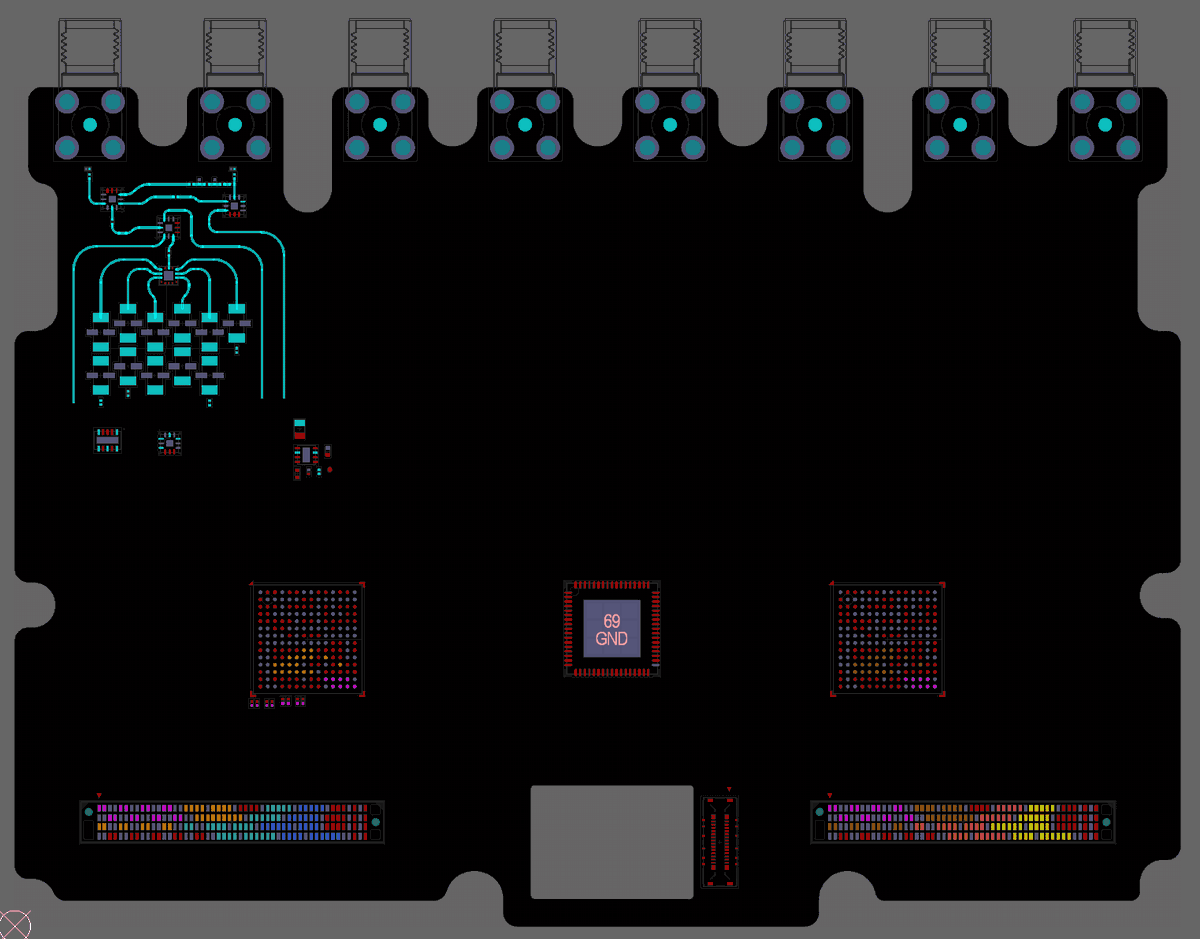
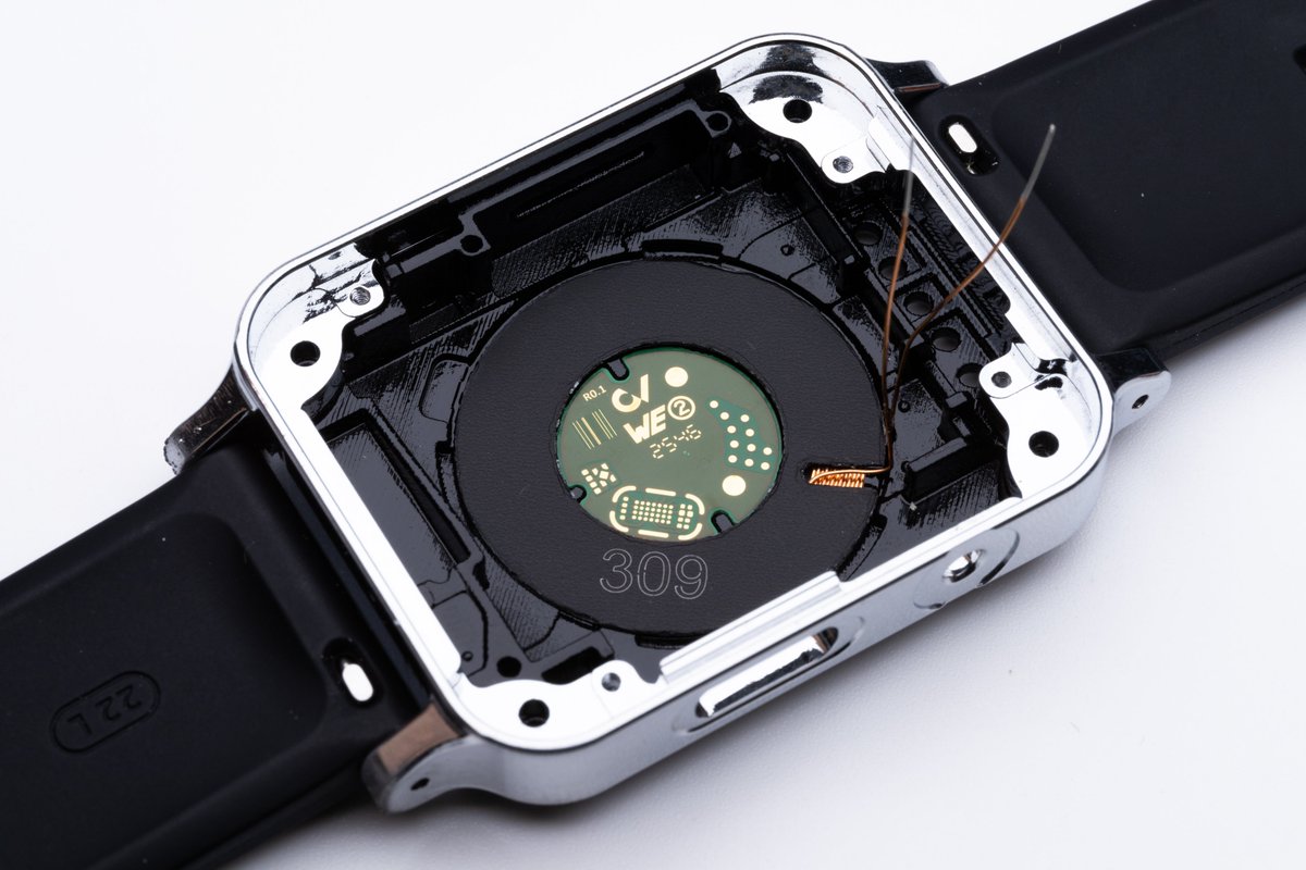
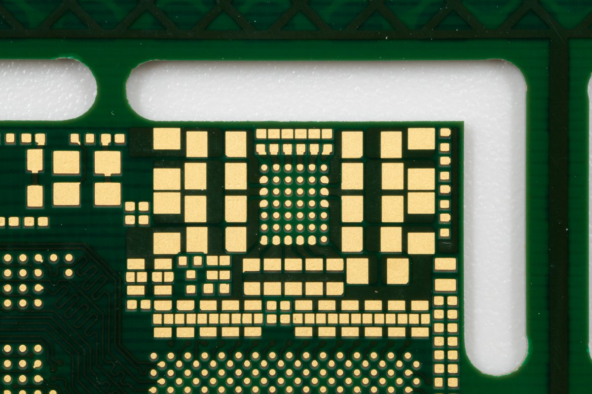
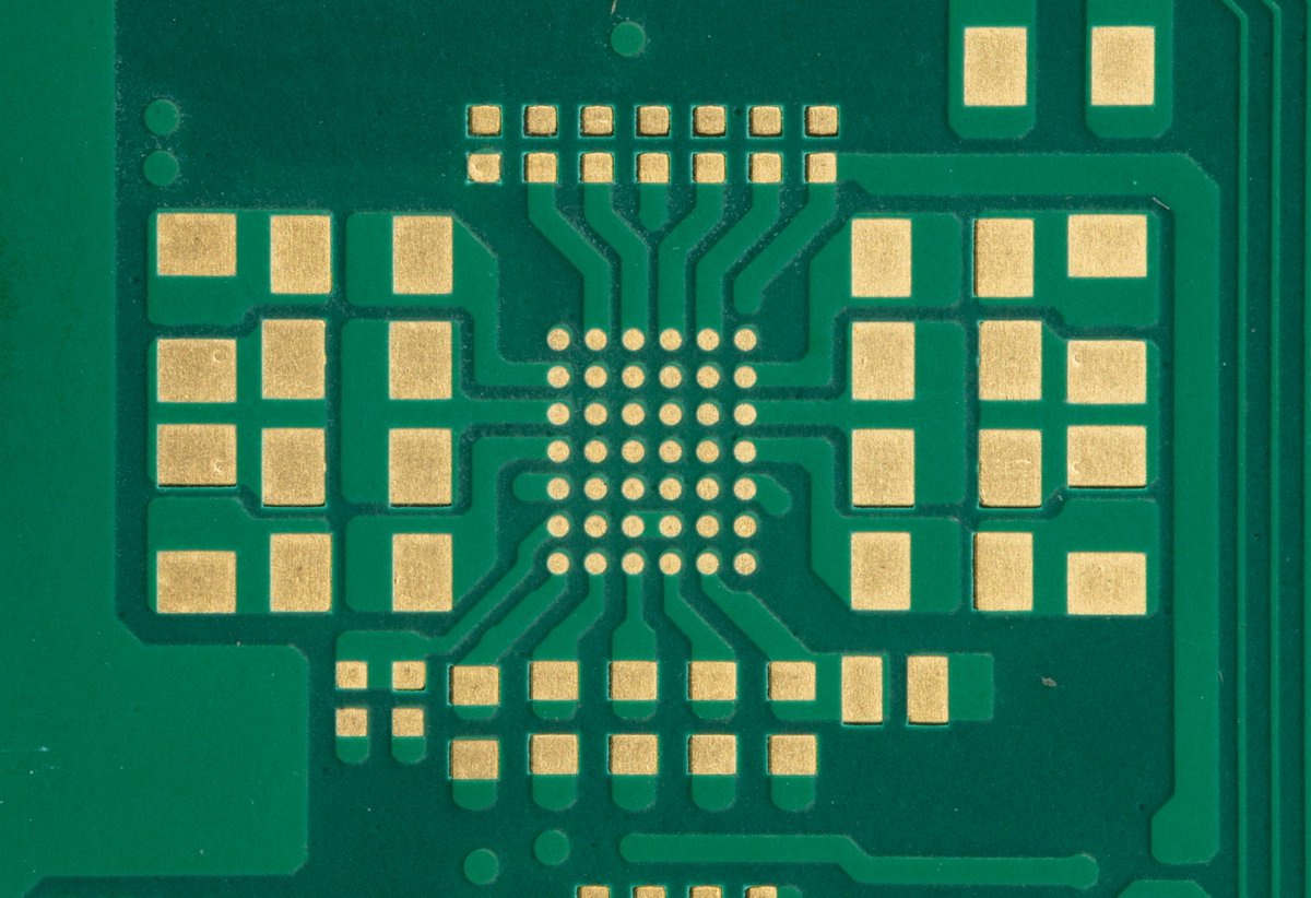
Using Blender and the layout data of a PCB, we can deconstruct an image of the PCB to reveal its inner copper layers 🔍
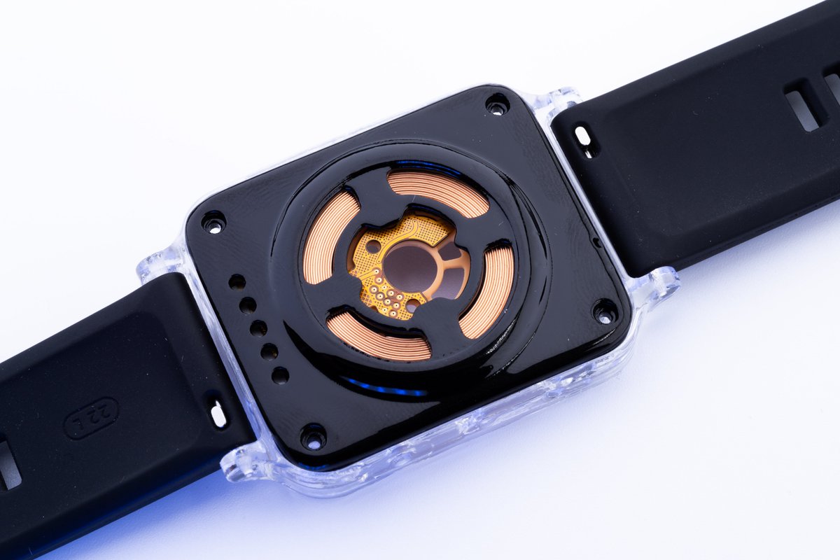
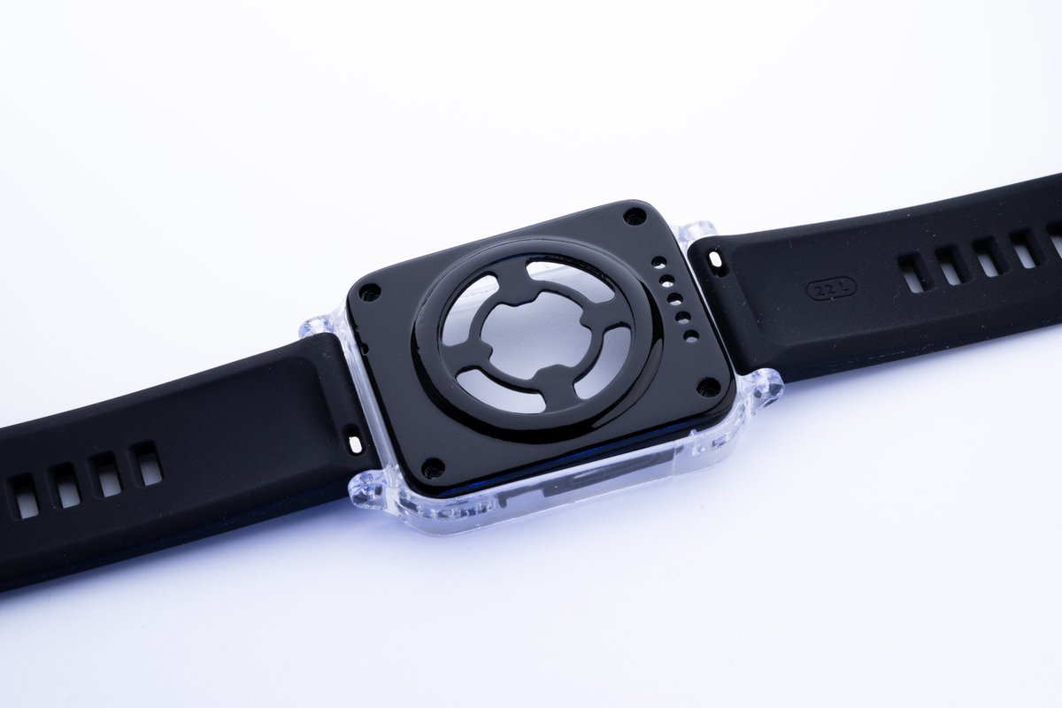
While I was waiting for the machined smartwatch case, I decided to test it with a transparent, 3D-printed enclosure. It might look interesting once all the internals are assembled

A good example of when to use soldermask defined pads... Especially when using VIPPO and the VIA is larger than the original pad, soldermask defined footprints have a higher manufacturing yield. The two images show the same footprint; one is soldermask-defined, while the other is…
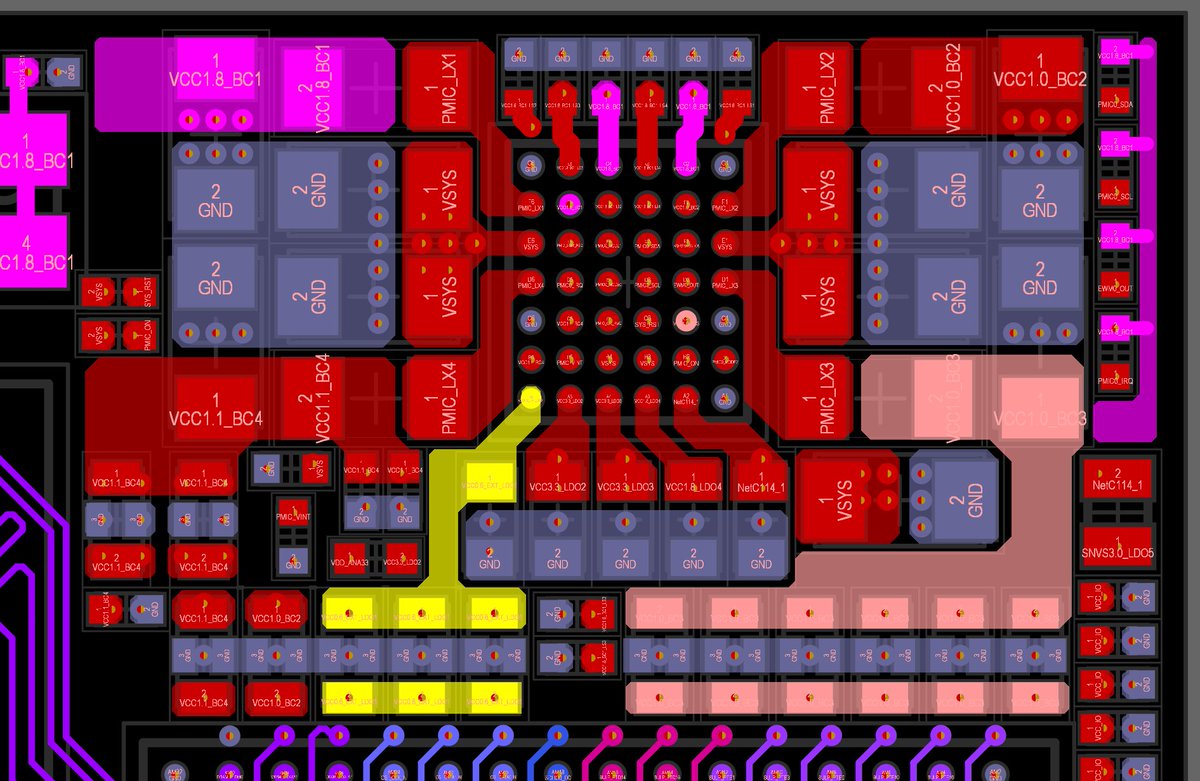
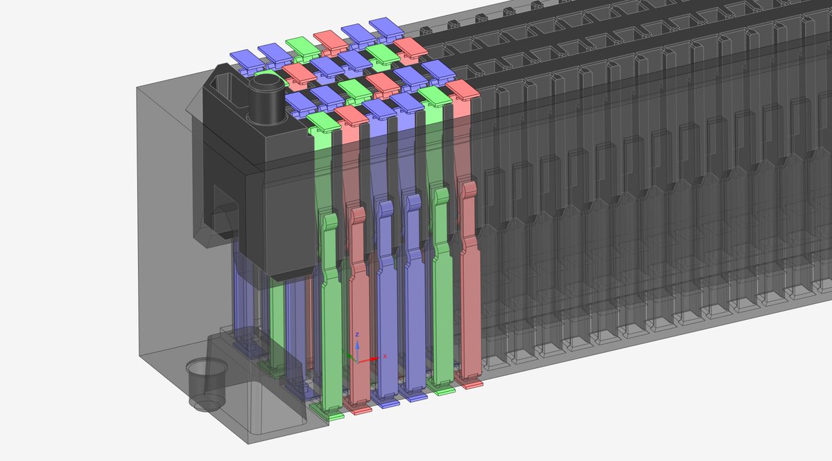
There is very little space in the AFE module for the Framework laptop SDR. I have started redesigning the floorplanning of the AFE module to improve channel isolation. I'll probably move some branches of the filter banks to the bottom of the PCB to create enough space for…


United States Trends
- 1. Markstrom N/A
- 2. Tyrese Maxey N/A
- 3. Dunesday 1,377 posts
- 4. Christmas Eve 130K posts
- 5. Insurrection Act 10.5K posts
- 6. Arsenal 173K posts
- 7. Southern Miss 1,306 posts
- 8. Western Kentucky N/A
- 9. Eric Gordon N/A
- 10. PGA Tour 1,065 posts
- 11. Toledo 9,567 posts
- 12. Brooks Koepka 1,250 posts
- 13. Because Chicago 1,798 posts
- 14. Ryan Leonard N/A
- 15. Jamie Benn N/A
- 16. Joel Embiid N/A
- 17. Lola Vice N/A
- 18. Brian's Song N/A
- 19. #drwfirstgoal N/A
- 20. Curtis 9,525 posts
You might like
-
 Mirosław Folejewski (Mirkotronics)
@Mirko_DIY -
 Sipeed
@SipeedIO -
 MangoPi🐧
@mangopi_sbc -
 Carl Bugeja
@BugejaCarl -
 Greg
Greg
@GregDavill -
 KiCad PCB
@kicad_pcb -
 Machdyne UG
@machdyne -
 Robin Reiter
@robin7331 -
 Mike
Mike
@mikerankin -
 Ivan Kuleshov
@Merocle -
 Matthew Venn
@matthewvenn -
 Cyber City Circuits
@MakeAugusta -
 Weston Braun
@WestonBraun -
 will whang🌻
@will_whang -
 arturo182 is on Bluesky now
@arturo182
Something went wrong.
Something went wrong.